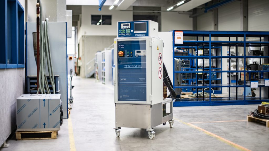
The layout of
Induction systems
Many parts – forming a unified whole
Converters, inductors, temperature monitoring – and what exactly do induction systems really look like? Here we describe the layout: which parts belong to a complete induction system and which tasks they fulfil.
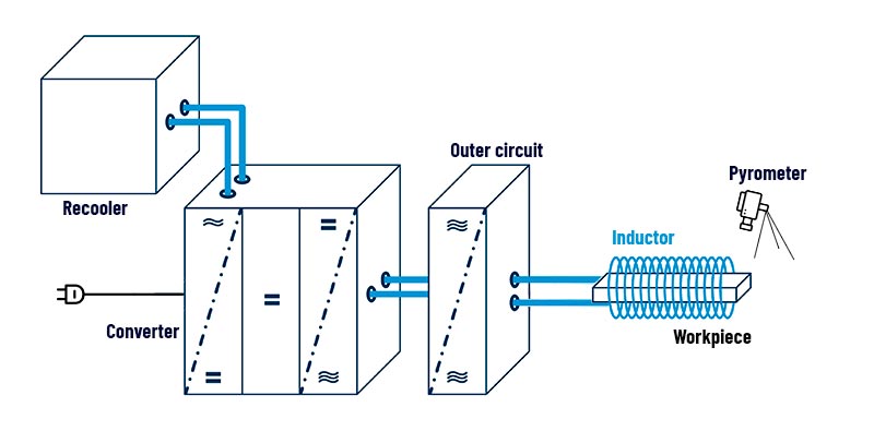
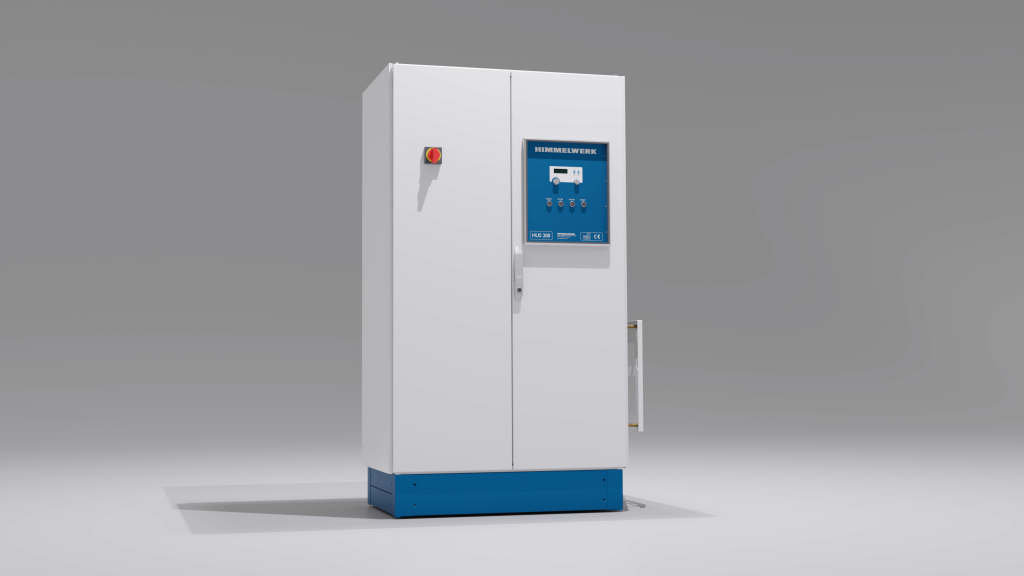
The Converter
General characteristics of a converter:
- Provides the necessary energy
- Determines the possible working frequency
- Outputs 2 kW to 250 kW
- Frequency range: 4 kHz to 2 MHz
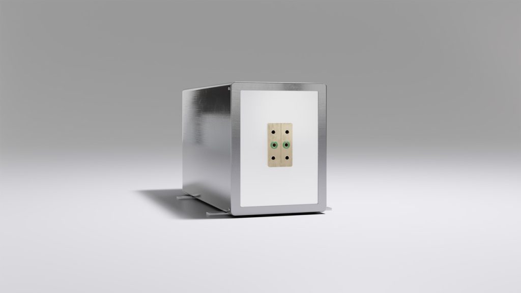
The outer circuit
Tasks of the outer circuit:
- For the connection of the inductor
- Is equipped with capacitors
- Change of capacitor assembly for tuning the frequency possible (depending on the converter)
Properties of the Himmelwerk outer circuits:
- Easy to maintain
- Water-cooled
- Compact design for space-saving integration
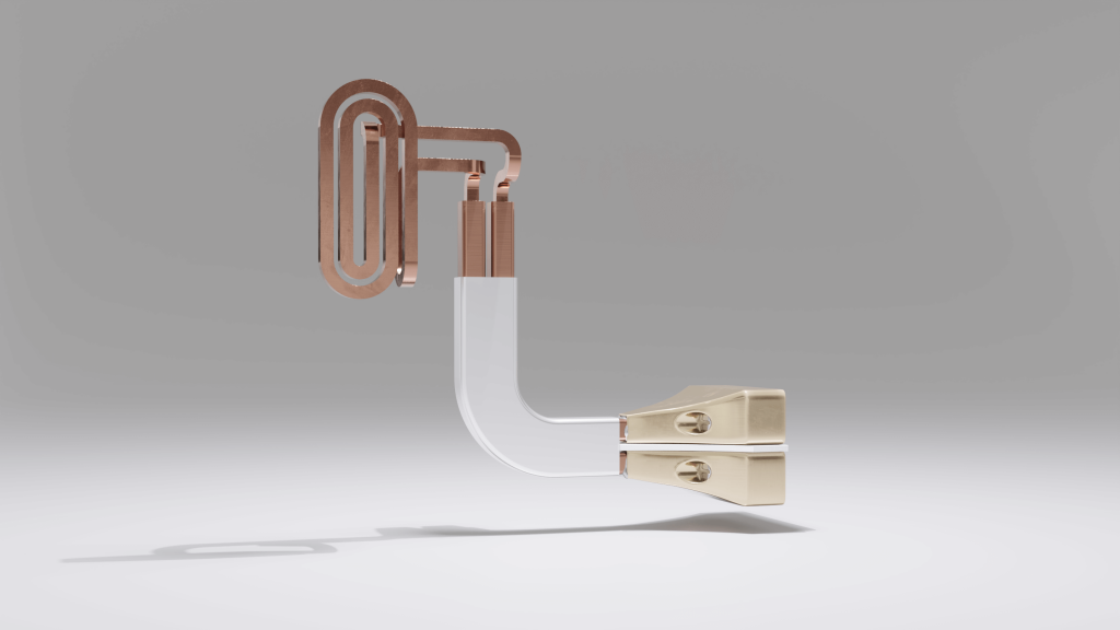
The inductor
Structure of an inductor:
- Water flowing through copper pipe
- Geometry is adapted to the component
- Exact adaptation to component guarantees high efficiency
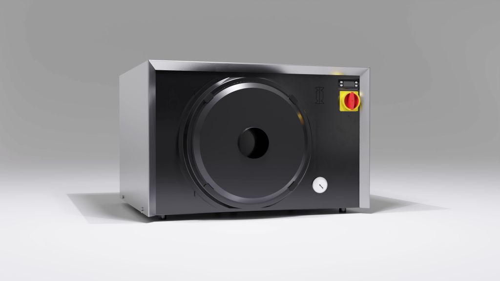
The water cooler
Task:
- Closed system for cooling the converter, outer circuit and inductor
- Ensure a closed cooling water circuit
- Maintain the quality of the cooling water
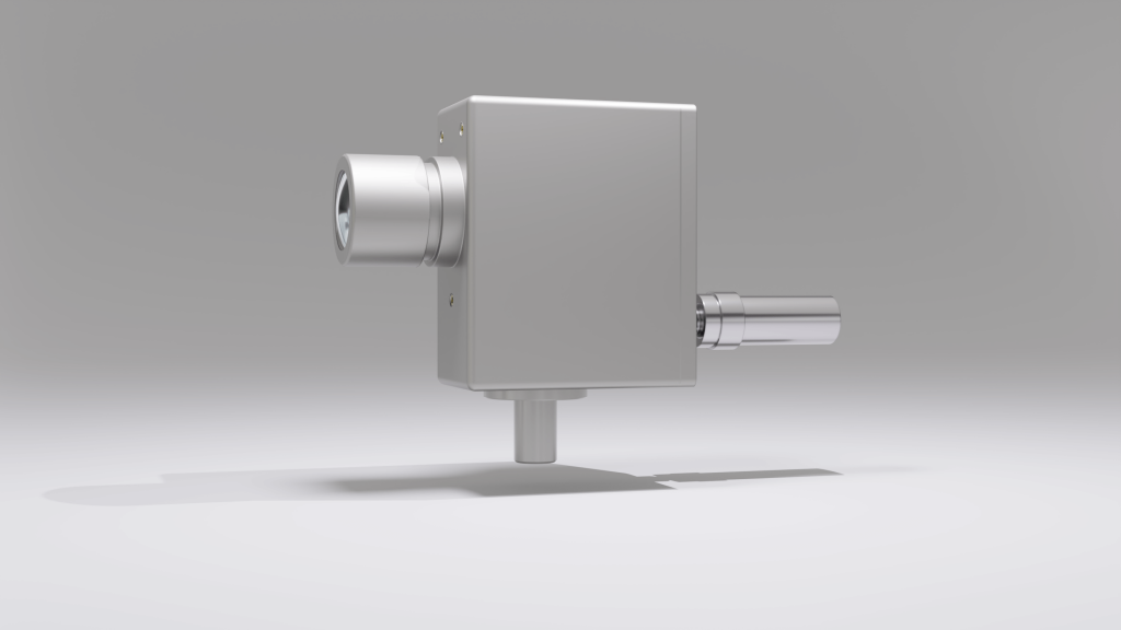
The pyrometer
Task:
- Device for no-contact measurement and regulation of the component temperature
- Application ranges between 50 and 3000 °C surface temperature possible
The Smart Upgrade
Unique to Himmelwerk: the Smart Upgrade, which allows AI-based verification and checking of compliance with specified limit values for induction heating.
- A retrofit solution for all AI-based converters
- Monitoring the inductive processes
- Identification of error sources